1. Creating a floor plan
Click Main menu / Stock management / Storage locations and shelves / Floor plan designer (the menu is in the Additional data section) to open the designer. On the left select the Site, then click the New floor plan button. Enter the Name (required), the Width and Height of the floor plan in centimeters and the Grid size (the step of snapping, default 50 cm). If a site has several floor plans, switch between them by clicking in the list on the left. The screenshots were taken from the Hungarian interface.
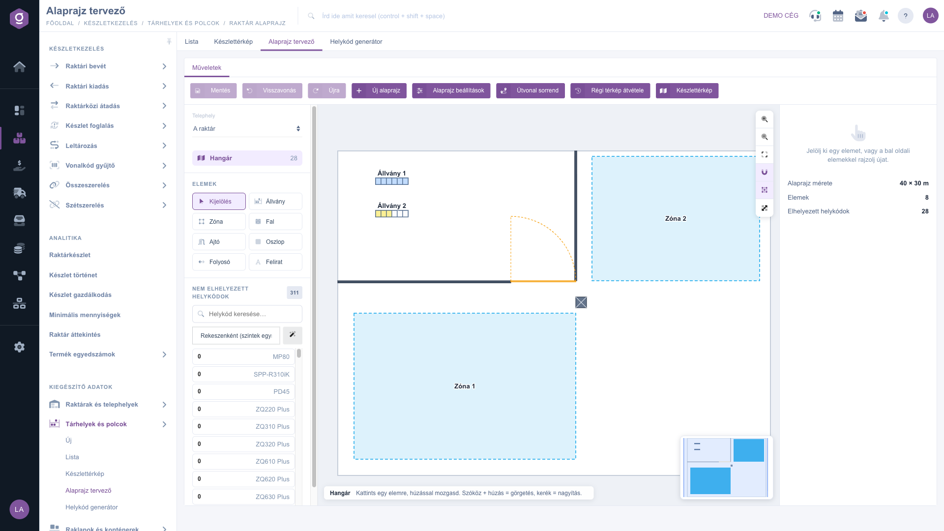
Floor plan designer – finished floor plan
2. Drawing elements
In the Elements panel on the left choose the type of the element, then drag the mouse over the floor plan; if you just click, the element is placed in its default size. When to use which:
- Rack: a shelf system with bays and levels; you can assign location codes to it. Draw most of your elements with this.
- Zone: a larger area (for example goods receipt, packing). You can set it to a single location position (1×1) if the area means a single location code.
- Wall, Door, Pillar: elements only for orientation, no location codes belong to them.
- Aisle: a striped band for the traffic route.
- Label: free text on the floor plan (for example DISPATCH).
3. Editing elements
Click an element to select it (select several with Shift or Ctrl, or with a frame dragged from an empty area). You can move a selected element by dragging (a pink guide line along the grid and neighboring elements shows the alignment; hold Alt to turn it off), resize it with the small squares and rotate it with the circle above (it sticks at 90-degree positions; hold Shift to rotate in 15-degree steps). In the panel on the right you can also enter the Name, X, Y, Width, Height, Rotation and Color exactly.
- Keys: V – select tool, R – rotate by 90 degrees, Del – delete, arrows – move by one grid step (with Alt by 1 cm), Ctrl+C / Ctrl+V / Ctrl+D – copy, paste, duplicate, Ctrl+A – select all, Ctrl+Z / Ctrl+Y – undo, redo, Ctrl+S – save, Space + drag – pan the view, Esc – release the tool.
- Duplicate in a row: makes the given number of copies of the selected element with the given gap and direction – ideal for building rack rows quickly. The names of the copies continue numbered (Rack 1, Rack 2…).
- Align and distribute: when several elements are selected, you can align them left, right or to the center in the right panel, or distribute them evenly.
- Lock: a locked element cannot be moved by accident (it is worth locking the walls).
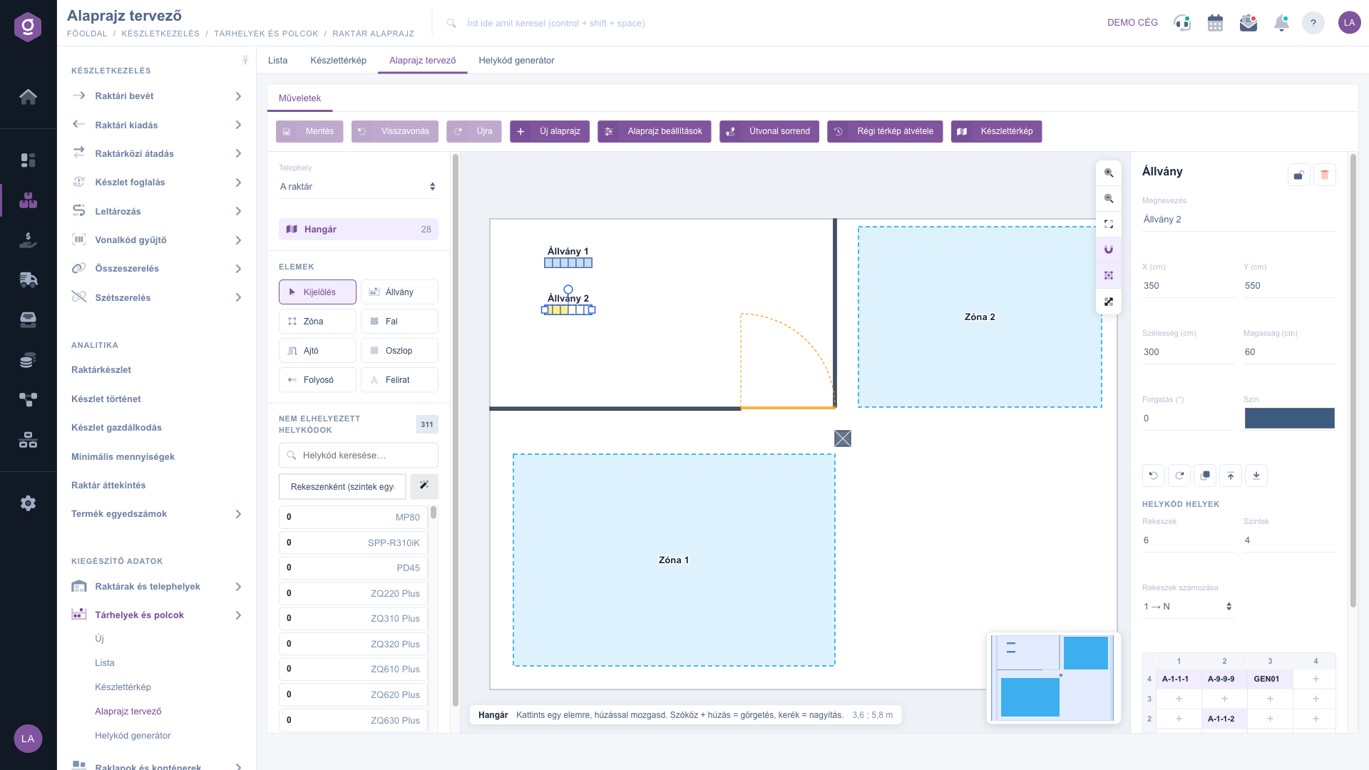
Floor plan designer – properties of the selected rack
4. Assigning location codes to a rack
Select a rack. In the Location positions section on the right enter the number of Bays (columns) and Levels, and the direction of the Bay numbering (1 → N or N → 1). A table appears below: the columns are the bays, the rows are the levels (the top level is at the top). You can fill it in three ways:
- By clicking: click an empty cell (marked by an orange frame), then the location code in the Unplaced locations list on the left. The system moves on to the next free position, so you can quickly go through a series. This is the most precise way when the order is not regular.
- By dragging: drag the location code from the list directly onto the cell. Good for placing a single location code.
- With auto fill: after choosing the Fill order (By bay (levels one after another) or By level (bays one after another)), the Auto fill button places the location codes of the list one after another into the free positions of the rack. Choose it when the names of the location codes are already in order (the list is sorted by barcode) and they just have to be poured onto the rack.
The cell shows the name of the location code; with the × sign you can detach the location code (it is not deleted, it returns to the unplaced list). With the Capacity for all locations field you can set the capacity of all location codes of the rack at once, and the Generate locations link takes you to the Location generator to create the missing location codes.
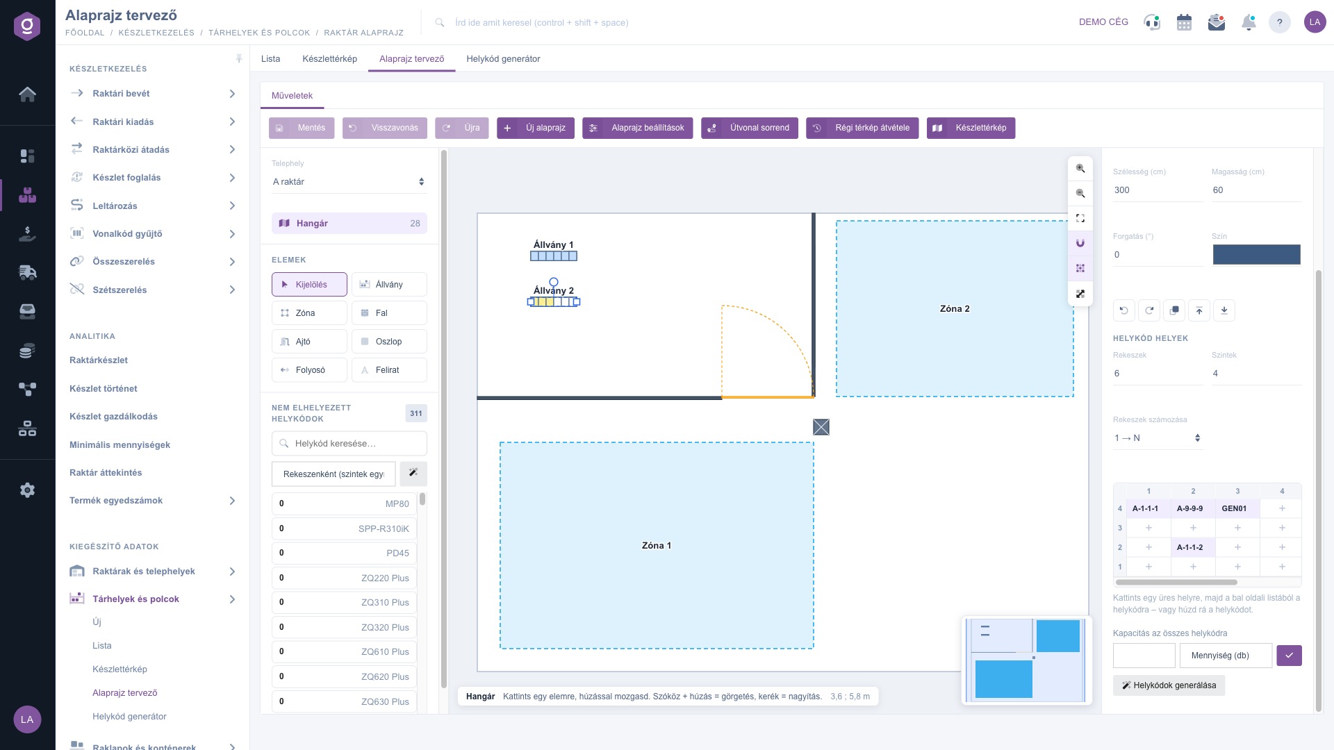
Floor plan designer – table of location positions
5. Saving
Click the Save button (or press Ctrl+S). The changes are saved in one step: either everything succeeds or nothing. Until saving you can step through the history with the Undo and Redo buttons. If you close the page without saving, the system warns you and offers to restore the draft the next time you open it. If a colleague modified the same floor plan in the meantime, saving does not overwrite their work but reports the conflict and asks you to reload.
6. Background image, scale
With the Floor plan settings button you can change the name, the dimensions and the grid, and you can also upload a Background image (PNG, JPG or GIF), for example a scanned architectural plan. Set the Background opacity slider and draw over it. If the size of the image does not fit, use the Calibrate scale button: click two points of the image whose real distance you know, enter it in meters, and the image is set to the right size. Uploading the background is saved immediately, so first save the other changes of the floor plan.
7. Route order and importing the old map
The Route order button calculates a snake-shaped walking order for the location codes from the floor plan and writes it into their order (distance) field. Enter the Band height (the band of rack rows next to each other), the side of the Start (top or bottom), the First number and the Step, check the result with the Preview button, then save it with Apply. Note: this also changes the order of the picking list. The Import old map button is visible only if the site had a placement in the old (visual map) tool: it imports them as zones into a new floor plan, the original data is not modified.
Tip
To build a whole rack row quickly, draw one rack, enter the number of bays and levels, then use the Duplicate in a row function (for example 8 pieces, with a 150 cm gap downwards). After that create the location codes for each rack with the Location generator and let the system assign them to the bays of the rack automatically.